Mail Delivery Rover
Designed and Implemented by
Shichen Zhang(sz555), Jiayang Wang(jw2533)
12/12/2019
Demonstration Video
Introduction
As we all know, when deliverymen pick up your mails, they would be sent to a local post center and sorted to different area corresponding to the destination of each mail. Normally this job is done by post offices staff and would cost a lot of time and labor. We are going to design a rover that can make this process automatic and smart. This rover will have different trays for different destinations, moves along a pre-defined line, when it reaches the corresponding area, it will drop the mail from the tray.
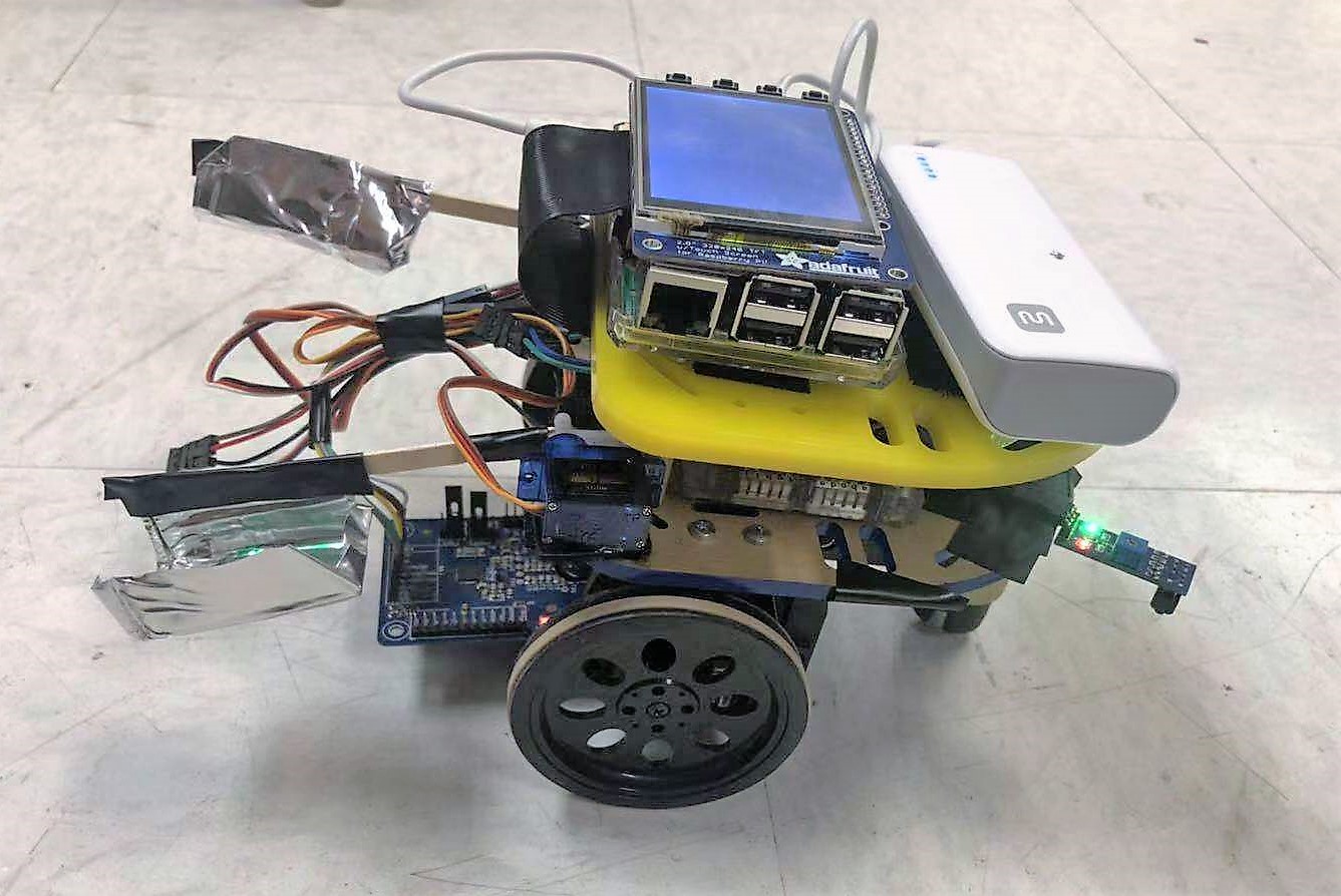
Figure 1. The Rover
Project Objective:
- IR sensor configuration and line following implementation
- RFID receiver configuration including reading
- Standard servo control to drive the mail trays
- Car moving control
- Remote display and control
- Emergency STOP and resume
- Automatic operation log record
- Signal lights to show operation status
Design & Testing
- Hardware
The hardware design of our project includes the Raspberry Pi, two IR sensors, two continuous servos, two standard servos, RFID, two trays and two LED light.
For IR sensors, we use the OSOYOO TCRT sensors. These sensors are composed of an integrated combination of PD (photo diode), IRED (infrared emitting diode) and signal processing circuit. They can detect the object between distance of 1-25mm, and can also be used to detect black lines. These sensors have the sensitive control which can help us to change its threshold deal with different distance. Since we can only assemble the IR sensors on the board of the robot, we need to calibrate the threshold to make it can distinguish the black line in the certain distance. We use two IR sensors to make the line follower, which they will always try to keep the black line between the two IR sensors when the robot moves. The IR sensor has the digital output, it would output the high voltage when it detected nothing or black line and would output low voltage when it detected the object.
As for the four serovs, they were connected to different GPIO and they were powered by external batteries. To protect the Pi, we also connected the resistance with the GPIO. The two continuous servos were used to control the two wheels, and the two standard servos were used to control the tray. The continuous servos could be easily used for the clockwise or counter-clockwise rotate. The standard servos were connected with the trays and they would rotate 45 degrees to drop of the mail from the tray when reached certain destinations.
The RFID we use was PN532, it was based on PN532 chip and used to 13.56 MHz near field communication.This module was equipped with on-board antenna, so there was no external antenna coil. It was compatible with SPI, IIC interfaces to communicate. With the support of NFC library, Raspberry Pi could connect products with the function of NFC, thus it was easy to use. In our robot, it was used to recognize the tags that represent different locations. The RFID was put on the bottom of the robot, so it can easily detected the tags when it passed by. The RFID connection with the Raspberry Pi were shown below. Our breakout used the SPI connection, there were also other connections that you can choose. At the beginning of our project, we planned to use the camera to recognize the destination, but we changed to use the RFID because if we want to recognize the destination using the camera, it would always be turned on, and it really waste a lot of power for this robot.
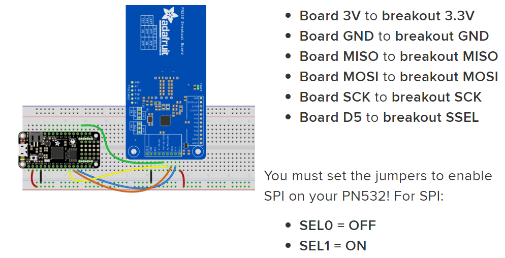
Figure 2. RFID receiver pinout
There were also two LED lights, they were all connected with different GPIOs. When the robot was moving, the red light would blink. When it detected a certain destination, the read light would turn off and the green light would turn on. Using these two lights as signal, we can easily know the states of the robot
- Software
Basic logic
The whole software logic image is as below. We used Python with two IR sensors to detect if the front part of the rover is currently exactly above the line, inclined to left, of inclined to right. We took advantage of the Adafruit CircuitPython library and PN532 module to read information of different tags. Once the rover is powered up, the system configuration is first initiated, including each GPIO pin configuration, Pygame rendering, and SPI connection that used by RFID receiver. Then the rover would stay at its position waiting START command. Once started, there would be a loop to control all kinds of parts on the rover. In a single circle of the loop, first the system would sleep 0.1 sec to hold current wheels status in order to maintain moving action for an appropriate duration. Then the rover would monitor remote control input, there would be 3 different cases:
1.No command input. This means continue work. Then the function “FollowLine” would be called. This function would adjust moving direction by control two wheels according to signal collected by two IR sensor to indicate current position relative the line below it. Then a tag number would be read by the RFID receiver. If the read tag number is one of our pre-defined destination number, the standard servo corresponding to this tag would drive its tray to drop off mail. If it is not any of the destination number, just go into another circulation.
2. If input command is Emergency STOP, all the wheel would be set to stop. The rover would stay at its current, all functions would be paused. This function is designed to solve emergency problems whic
3. If the input command is QUIT, the whole system would be shutdown. The rover will be stopped and stay.
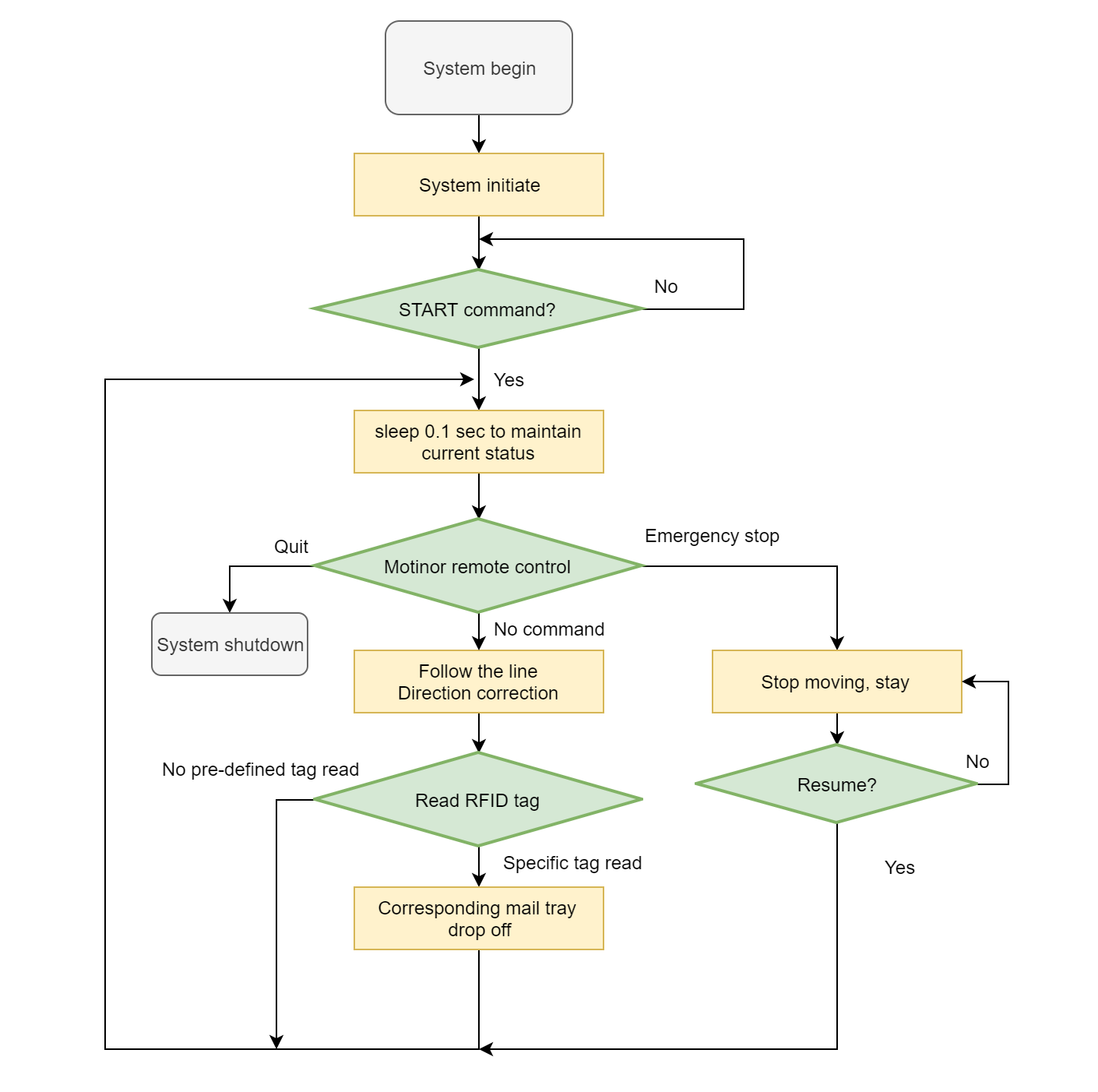
Figure 3. The whole program working flowchart
Line Following
All the moving actions of our rover are based on current relative position to the line below the rover. So the wheel actions, including ratate direction and speed are controlled according to input signals of two IR sensors.
The continuous servo that used to drive the wheels are controlled by software-based PWM. Different values of duty cycle of the PWM decide rotate direction and speed. After our calibration, we set our continuous servo that when PWM duty cycle value is smaller than 7, it would rotate clockwise, the smaller the value, the faster the rotation. Inversely, when the PWM duty cycle value is larger than 7, the servo would rotate counterclockwise, the larger the value, the faster the rotation. So we set 7 as the duty cycle balance point which results in a nearly stopped servo, so a nearly stopped wheel.
As for the IR sensor, by calibrating the threshold of it, we got a LOW input when the sensor is not above the line, and a HIGH input when the sensor is exactly above the line. We put one IR sensor at the left side of the rover and one IR sensor at the right side of the rover. By doing this, we can combine the two input from the sensors to decide if the rover is exactly above the line or inclined.
So in the “followLine” function, if all the two sensors are not in the line, it means we are on the line so just move forward. If left sensor is on the line, but right sensor is not on the line, which indicates the rover is inclined to right, just tune left. Similarly, if the left sensor is not on the line while the right sensor is on the line, which indicates the rover is inclined to the left, just turn right. Else, just stay.
RFID Recognition
For the RFID receiver, we chose to use SPI interface to connect it to the Raspberry Pi because this kind of connection is more suitable for our model of RFID receiver and the Raspberry Pi. In order to read tags by the receiver, we set up the SPI connections and configured PN532 to communicate with MiFare tags like below :
        # SPI connection:
        spi = busio.SPI(board.SCK, board.MOSI, board.MISO)
        cs_pin = DigitalInOut(board.D5)
        pn532 = PN532_SPI(spi, cs_pin, debug=False)
        ic, ver, rev, support = pn532.get_firmware_version()
        print('Found PN532 with firmware version: {0}.{1}'.format(ver, rev))
        # Configure PN532 to communicate with MiFare cards
        pn532.SAM_configuration()
Once we read a valid tag number, formatting it and return to the main loop.
Standard Servo Control
To control mail trays to drop off mail when got appropriate position, we decided to use standard servos to drive the mail trays. When a specific is detected, the blink led which indicate the rover is following the line will be stopped and the green led would be turned on to indicate a tag detected and is delivering mail. The value of the duty cycle in standard servos indicates different positions(angles). So we manipulate the duty cycles to control standard servos.
Issues & Solutions
SPI interface conflict
One issue we encountered is that before we designed the RFID module of the rover, we both have local monitor using piTFT screen and a remote monitor. Then we attached the wires the RFID receiver requires with SPI interface to the Raspberry Pi. However, when we build a test program to test the RFID function, the system couldn’t find the RFID receiver. Then we double checked both the wire connection and program design, but both of them works well. Then we tried our best to find bugs when we cannot find the receiver. After a long time of searching and thinking, we found that piTFT also uses SPI interface to connect.
The image below shows the wire attachment of the RFID receiver.
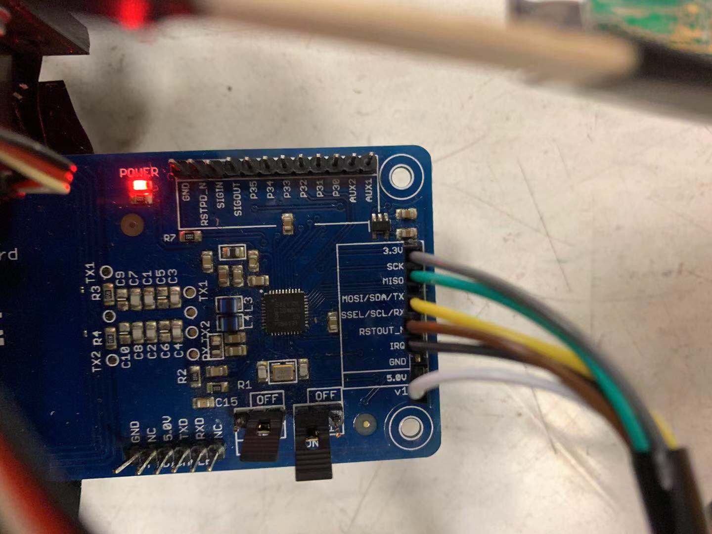
Figure 4. RFID receiver wire attachedment
To figure this out, we have two choices, either enable second set of SPI interface in Raspberry Pi or abandon the piTFT connection. We considered that if the rover is in working mode, it would move along a line and people don’t need to and can’t make it to stare at the small screen on the rover. Therefore, we decided to abandon the piTFT screen and choose to use the SPI interface for RFID module.
IR sensor calibration
The second issue was that it was difficult to keep IR sensors in a fixed location. We used tape to stick them on the board, but they always changed their position after some time. They could not recognize the black line when the position changed. The better solution was to change them to a lower position, so they would be not sensitive to the changing of the position.
The IR sensors position and height to the ground we employed is as the image below:
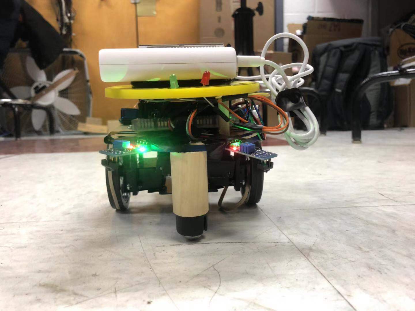
Figure 5. IR sensors position and height
Results & conclusions
We successfully finished our project. Our mail deliver rover could follow the line and when it detected the tags on the ground, the standard servos would rotate the corresponding trays and drop the mails on that tray to the ground. Then it would move to the next destination until receive a stop command.
Future Work
In our future work, we would like to increase the move speed for our robot. The big challenge of increasing the speed is to make the control, each turn, become more accurate. The control method we use now is very simple, maybe we can use the PID control for each turn in the future. Using this high level way to control also need more feedback information, like how far the sensor away from the balck line, so more accurate sensors are needed.
To make the moving of the robot more robust, we would also like to change the IR sensors to the lower position. In this way, it would not easily be affected by the light or other shadows, and it can move in different environments.
The tray size can be increased in the future. We can better design a big tray to be connected with the standard servo and make the robot can really deliver the mail.It might need some mechanical techniques and better servo to do that.
Work Distribution
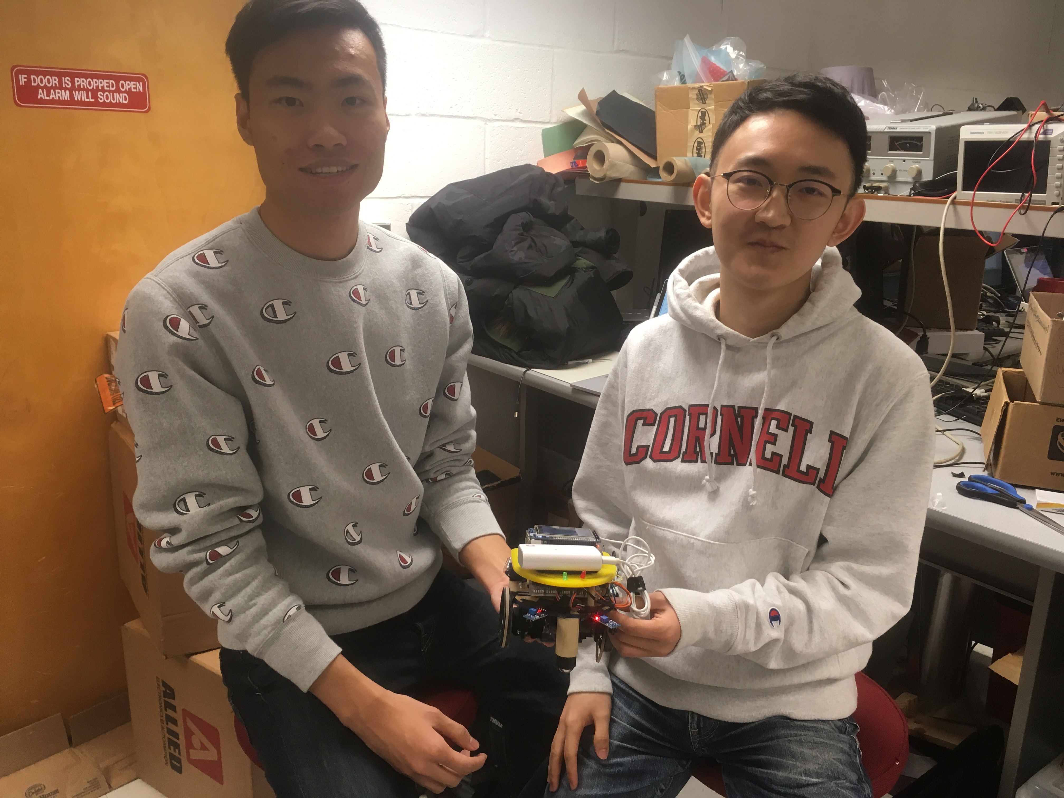
Figure 6. Project group picture
Jiayang Wang
jw2533@cornell.edu
Designed the overall software architecture and tested thh whole system
Shichen Zhang
sz555@cornell.edu
Designed the circuit and tested the over all system
Parts List
| Components | Cost | Number | Total Cost |
|---|---|---|---|
| Raspberry Pi Model 3 B+ | $35 | 1 | $35 |
| TCRT 5000 IR Sensors(OSOYOO) | $1.2 | 2 | $2.4 |
| PN 532 RFID Module | $36 | 1 | $36 |
| RFID Tags | $0.2 | 3 | $0.6 |
| LED Lights | 2 | Provided in lab | |
| Power Bank | 1 | Provided in lab | |
| AA Battery | 4 | Provided in lab | |
| Standard Servos | 2 | Provided in lab | |
| Continuous Servos | Provided in lab | ||
| Final Cost | $74 |
Code Appendix
1 2 3 4 5 6 7 8 9 10 11 12 13 14 15 16 17 18 19 20 21 22 23 24 25 26 27 28 29 30 31 32 33 34 35 36 37 38 39 40 41 42 43 44 45 46 47 48 49 50 51 52 53 54 55 56 57 58 59 60 61 62 63 64 65 66 67 68 69 70 71 72 73 74 75 76 77 78 79 80 81 82 83 84 85 86 87 88 89 90 91 92 93 94 95 96 97 98 99 100 101 102 103 104 105 106 107 108 109 110 111 112 113 114 115 116 117 118 119 120 121 122 123 124 125 126 127 128 129 130 131 132 133 134 135 136 137 138 139 140 141 142 143 144 145 146 147 148 149 150 151 152 153 154 155 156 157 158 159 160 161 162 163 164 165 166 167 168 169 170 171 172 173 174 175 176 177 178 179 180 181 182 183 184 185 186 187 188 189 190 191 192 193 194 195 196 197 198 199 200 201 202 203 204 205 206 207 208 209 210 211 212 213 214 215 216 217 218 219 220 221 222 223 224 225 226 227 228 229 230 231 232 233 234 235 236 237 238 239 240 241 242 243 244 245 246 247 248 249 250 251 252 253 254 255 256 257 258 259 | import time import sys import pygame import os import RPi.GPIO as GPIO from pygame.locals import * # for RFID import board import busio from digitalio import DigitalInOut from adafruit_pn532.spi import PN532_SPI # pygame initial pygame.init() os.putenv('SDL_VIDEODRIVER','fbcon') os.putenv('SDL_FBDEV','/dev/fb1') os.putenv('SDL_MOUSEDRV', 'TSLIB') os.putenv('SDL_MOUSEDEV', '/dev/input/touchscreen') GPIO.setmode(GPIO.BCM) # Set for broadcom numbering not board numbers... # red led GPIO.setup(16,GPIO.OUT) red_led = GPIO.PWM(16, 4) red_led.start(70) # green led GPIO.setup(21,GPIO.OUT) green_led = GPIO.PWM(21, 50) #green_led.start(70) GPIO.setup(17, GPIO.IN, pull_up_down=GPIO.PUD_UP) # set up broadcom number 17 as input GPIO pin, as pull up network) # setup GPIO output pins, channels, frequency and duty cycle. # standard servo GPIO.setup(20,GPIO.OUT) standard_servo=GPIO.PWM(20,50)# 50hz frequency standard_servo.start(12)# starting duty cycle ( it set the servo to 0 degree ) # standard servo 2 GPIO.setup(6,GPIO.OUT) standard_servo_2=GPIO.PWM(6,50)# 50hz frequency standard_servo_2.start(12)# starting duty cycle ( it set the servo to 0 degree ) # left servo GPIO.setup(26, GPIO.OUT) servo_left=GPIO.PWM(26,50) servo_left.start(7) # setup GPIO output pins, channels, frequency and duty cycle. # right servo GPIO.setup(4, GPIO.OUT) servo_right=GPIO.PWM(4,50) servo_right.start(7) # left IR sensor GPIO.setup(23, GPIO.IN, pull_up_down=GPIO.PUD_UP) # right IR sensor GPIO.setup(12, GPIO.IN, pull_up_down=GPIO.PUD_UP) # half speed dc_clockwise = 6.85 # clock dc_counterclockwise = 7.15 # counter clock # Set basic parameters pygame.mouse.set_visible(True) size = width, height = 320, 240 screen= pygame.display.set_mode((320, 240)) black = 0, 0, 0 WHITE = (255, 255, 255) red = 255,0,0 green = 0,255,0 my_buttonfont = pygame.font.Font(None, 30) my_displayfont = pygame.font.Font(None, 20) my_buttons = { 'quit':(290, 210),'start':(30,210)} def moveForward(): servo_left.ChangeDutyCycle(dc_counterclockwise) servo_right.ChangeDutyCycle(dc_clockwise) def turnLeft(): servo_left.ChangeDutyCycle(dc_clockwise + 0.04) servo_right.ChangeDutyCycle(dc_clockwise + 0.04) def turnRight(): servo_left.ChangeDutyCycle(dc_counterclockwise - 0.09) servo_right.ChangeDutyCycle(dc_counterclockwise - 0.04) ''' line sensor feedback 1 - above line - HIGH 0 - no line - LOW left sensor | right sensor result 0 0 moveforward 1 0 () turnleft 0 1 () turn right ''' def followLine(): if GPIO.input(23) == GPIO.LOW and GPIO.input(12) == GPIO.LOW: print("move forward") moveForward() elif GPIO.input(23) == GPIO.HIGH and GPIO.input(12) == GPIO.LOW: turnLeft() print("turn left") elif GPIO.input(23) == GPIO.LOW and GPIO.input(12) == GPIO.HIGH: turnRight() print("turn right") else: servo_left.ChangeDutyCycle(7) servo_right.ChangeDutyCycle(7) print("stay") flag = False start = False # RFID # SPI connection: spi = busio.SPI(board.SCK, board.MOSI, board.MISO) cs_pin = DigitalInOut(board.D5) pn532 = PN532_SPI(spi, cs_pin, debug=False) ic, ver, rev, support = pn532.get_firmware_version() print('Found PN532 with firmware version: {0}.{1}'.format(ver, rev)) # Configure PN532 to communicate with MiFare cards pn532.SAM_configuration() def readtags() : uid = pn532.read_passive_target(timeout=0.5) if uid is None: return(-1) print('Found card with UID:', int(uid[0])) return(int(uid[0])) # loop control # main part while 1: time.sleep(0.1) for event in pygame.event.get(): if(event.type is MOUSEBUTTONUP): pos = pygame.mouse.get_pos() x, y = pos # start button if x >= 0 and x <= 60 and y >= 180 and y <= 240: time.sleep(0.2) flag=False # false - if press, then stop start=True if flag == False: # (160, 120) center of the screen # panic stop/ resume if ((x-160)*(x-160)+(y-120)*(y-120)) < 1600: flag = True servo_left.ChangeDutyCycle(7) servo_right.ChangeDutyCycle(7) elif flag == True: # true - if press, then run if ((x-160)*(x-160)+(y-120)*(y-120)) < 1600: flag = False followLine() # quit button if x >= 260 and x <= 320 and y >= 180 and y <= 240: servo_left.stop servo_right.stop GPIO.cleanup() sys.exit() # physical "Exit" button if(not GPIO.input(17)): servo_left.stop servo_right.stop GPIO.cleanup() sys.exit screen.fill(black) # motor control if flag == False: # render stop button pygame.draw.circle(screen,red,(160,120),40) text_surface = my_buttonfont.render('stop', True, WHITE) rect = text_surface.get_rect(center=(160,120)) screen.blit(text_surface, rect) # for p1(left wheel) dc_countclkwise - move forward # running if start == True: followLine() #time.sleep(0.02) tagid = readtags() if tagid == 149: red_led.stop() green_led.start(70) for i in range(200000): standard_servo.ChangeDutyCycle(9) for i in range(200000): standard_servo.ChangeDutyCycle(12) print ("NYC") for i in range(300): followLine() time.sleep(0.01) print("Push-out finished") green_led.stop() red_led.ChangeFrequency(4) red_led.start(70) elif tagid == 117: red_led.stop() green_led.start(70) for i in range(200000): standard_servo_2.ChangeDutyCycle(9) for i in range(200000): standard_servo_2.ChangeDutyCycle(12) print ("Los Angeles") for i in range(300): followLine() time.sleep(0.01) print("Push-out finished") green_led.stop() red_led.ChangeFrequency(4) red_led.start(70) # green resume state else: # resume pygame.draw.circle(screen,green,(160,120),40) text_surface = my_buttonfont.render('resume', True, WHITE) rect = text_surface.get_rect(center=(160,120)) screen.blit(text_surface, rect) for my_text, text_pos in my_buttons.items(): text_surface = my_buttonfont.render(my_text, True, WHITE) rect = text_surface.get_rect(center=text_pos) screen.blit(text_surface, rect) pygame.display.flip() servo_left.stop servo_right.stop GPIO.cleanup() sys.exit() |